Table of Contents
Components
This stage involves the following new components.
- RGB LED
All the colours of the rainbow!
So our RGB LED is essentially 3 LEDs in one - a red one, a green one and a blue one. By turning on certain combinations of these LEDs we can create lots of different colours. But first… how do we connect them to the Arduino?
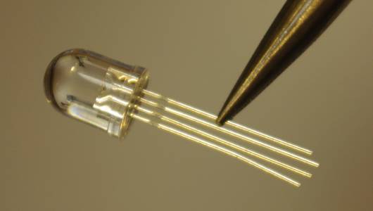
RGB LEDs typically have 4 leads. The longest one is the common positive lead shared by each colour of LED. The other 3 leads are the 3 negative leads of each of the red, green and blue LEDs inside. Like normal LEDs, RGB LEDs need resistors in series to stop too much current passing through. Again 100-300 ohms is good, and you'll need 3 of them.
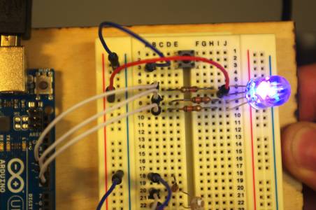
Connect your RGB LED to your Arduino using the breadboard.
Since each LED is connected to the Arduino with at its negative lead, the control for this LED is the opposite to the previous LEDs. In order to turn the LEDs on, you need to set the corresponding pins to the LOW (0V) value.
Even more colours!
So far we have 7 colours: red, green, blue, cyan, magenta, yellow and white. But how do we get more?
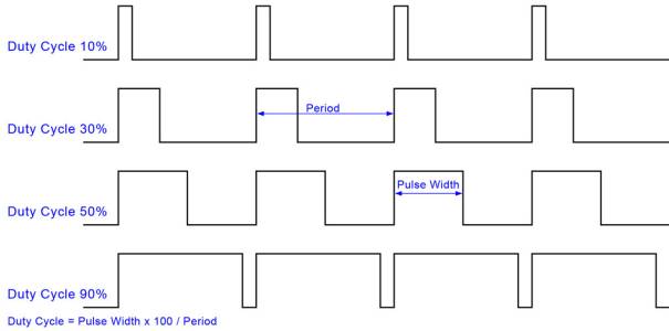
Well, if you can adjust the brightness of each of the red, green and blue components of the light, then you can get many more colours. You can do this with a technique called Pulse Width Modulation, or PWM. In fact, you've already done this in stage 1 when you set the frequency of the blinking light really high and it appeared to be constantly on at a reduced brightness. PWM is exactly that, with an added bit of flexibility - you can adjust the ratio between the time the LED is turned on, and the time the LED is turned off, giving continuous brightness adjustment.
PWM is achieved in Arduino through the analogWrite function. Instead of telling you how to do it though, we thought we'd get you to use the official Arduino documentation. It's useful stuff!
 | (1) Go to the Arduino website and click on reference. Find analogWrite and use it to fade in and fade out the red LED in the RGB LED. (2) Now do the same but with every LED in the RGB LED. You should get a white light fading in and out. (3) Now modify that so that each colour component fades in and out at a different rate. This should give you lots and lots of colours. |
My Eyes!
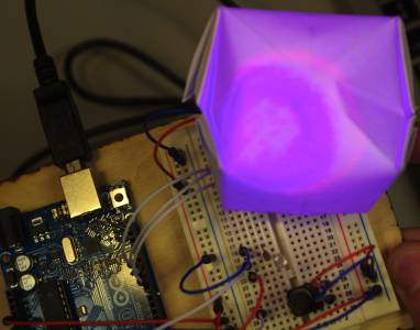
You might have noticed that the RGB LED is quite bright! To help diffuse the light and make the whole thing look a little prettier, we can encase the LED in a paper balloon. Grab a piece of paper and follow this video guide to making paper balloons.
When you've finished, put the LED through the hole in the balloon.
There… that's much prettier!
Portability
Ask for a 9V battery connector and use it to make your colour-changing mood lamp portable. This is done by connecting the black lead of the battery connector to a GND pin, and the red lead of the battery connector to the VIN pin.
Next Stage
Congratulations! Go to Stage 5


